
Hello and welcom to my first blog post in which I document my journey through a short project prototyping an RFID reader!
Table of Contents
- Part 1 - Vision and Structure
- Part 2 - Determining the Parts
- Part 3 - Building and Environment Setup
- Part 4 - Writing the Code
- Part 5 - End
Part 1 - Vision and Structure
The prototype developed in this project isn’t intended for real-world deployment, so it is on the simpler side and lacking practicality. It is designed as a learning experience, giving me exposure to new technologies. Still, here’s the basic structure:
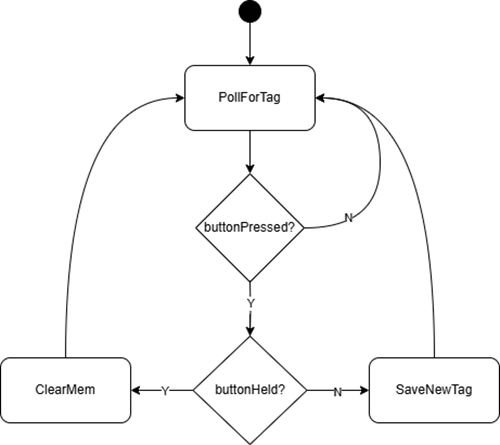
The integrated RFID reader will continuously poll for a tag. When a tag is read, it will confirm whether it is valid or invalid by comparing its ID with the tags stored in its flash memory. The user can also interact with the board via a button, allowing them to store the ID of the next tag read into flash memory or clear it entirely.
Here is a rough state diagram showcasing this process.
Part 2 - Determining the Parts
Here is a full list of components/tools used:
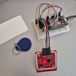
- ESP-WROOM-32
- PN532 RFID Reader
- Pushbutton
- Passive Buzzer
- Breadboard and Jumper Wires
- Soldering Kit
- Multimeter and Logic Analyzer
The most important decision I had to make in the initial stages of development was whether I was going to use an Arduino or ESP32. Although there were prebuilt Arduino libraries available, I decided to use ESP-IDF to prevent abstracting the lower-level concepts, even if that meant taking more time.
Initially, I didn’t expect much hardware debugging to be needed for such a simple project. Turns out I was wrong, and I needed a soldering kit, multimeter, and logic analyzer later on.
...
Assembly was as simple as expected.
For the PN532, 4 GPIO pins were used for SPI connection. There were two optional pins for extra functionality (RSTO and IRQ), but I decided not to use them (if I could go back though, I would use the IRQ pin because it makes things much simpler)
The RFID reader required through-hole soldering with header pins. Good thing I had some (minimal) experience with soldering.
Part 3 - Building and Environment Setup
Before coding the actual project, I had to briefly sidetrack to build and flash a provided example project on my board. This step was necessary because this was my first time with ESP32 microcontrollers. I used ESP-IDF to build and flash projects to my board, and will be keeping this same setup for the rest of the project.
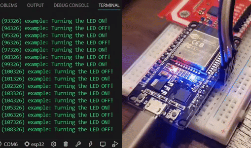
The example project simply blinks the on-board LEDs at even length time intervals. Here is the main function.
void app_main(void) {
    /* Configure the peripheral according to the LED type */
    configure_led();
    while (1) {
        ESP_LOGI(TAG, "Turning LED %s!", s_led_state == true ? "ON" : "OFF");
        blink_led();
        /* Toggle the LED state */
        s_led_state = !s_led_state;
        vTaskDelay(CONFIG_BLINK_PERIOD / portTICK_PERIOD_MS);
    }
}
I had a lot of issues with drivers and imports and had to troubleshoot for a while fixing everything, but eventually, I got build and flash to work successfully.
...
Now, I’ll describe how I organized the file structure of the project.
main -
    Common -
        Globals.h
        HardwareConfig.h
    Reader -
        PN532Drv.h
        PN532Drv.c
        ReaderApi.h
        ReaderApi.c
    Buzzer -
        BuzzerDrv.h
        BuzzerDrv.c
    Button -
        ButtonDrv.h
        ButtonDrv.c
    Storage -
        StorageApi.h
        StorageApi.c
    main.c
Though it may seem unnecessary for such a small project, I used a layered software architecture to organize my files. This helped me abstract unnecessary code and improve portability/reusability.
Part 4 - Writing the Code
Since I was not familiar with ESP-IDF, I had to allocate a lot of time to get familiar, so I will be omitting much of the boring information (reading documentation/datasheets, debugging, etc) and focus on how I structured the project and made coding decisions instead.
Here is my GitHub repository for the project and here is the user manual for the PN532 chip.
PN532Drv.c
The PN532Drv file contains the code that initializes SPI connection and transmits frames. This file would fall under the hardware abstraction layer (HAL) but it also contains lower-level bit manipulation as I used bit-bang SPI.
I initially tried the ESP-IDF SPI driver, but the PN532 wouldn’t respond reliably — even after continued debugging with a logic analyzer. I determined that there was a very specific timing requirement with the SS pin, so I had to stick with bit-bang for the project.
...
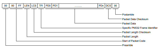
Here is the structure of the frames that the host and slave exchange during transmission. Other than the actual data, the frames contain pre/postambles, the length, and checksums.
void PN532_WriteCommand(INT8U *cmd, INT8U cmd_length) {
    INT8U frame[cmd_length + 9];

    // Start of frame
    frame[0] = PN532_DW;                                // Direction Byte
    frame[1] = PN532_PREAMBLE;                          // Preamble
    frame[2] = PN532_STARTCODE1;                        // Startcode
    frame[3] = PN532_STARTCODE2;
    frame[4] = (cmd_length + 1);                        // Length
    frame[5] = (INT8U)(~frame[4] + 1);                  // Length Checksum
    frame[6] = PN532_TFI;                               // Data (including TFI)
    memcpy(&frame[7], cmd, cmd_length);
    frame[7 + cmd_length] = PN532_TFI;                  // Data Checksum
    for (INT8U i = 0; i < cmd_length; i++) {
        frame[7 + cmd_length] += frame[7 + i];
    }
    frame[7 + cmd_length] = (INT8U)(~frame[7 + cmd_length] + 1);
    frame[8 + cmd_length] = PN532_POSTAMBLE;            // Postamble
    // End of frame

    // Sending frame via SPI
    gpio_set_level(READER_SS_PIN, 0);
    ets_delay_us(100);
    for (int i = 0; i < cmd_length + 9; i++) {
        SPI_writeByte(frame[i]);
    }
    gpio_set_level(READER_SS_PIN, 1);
    ets_delay_us(50);
}
The PN532 requires a direction byte at the start of each frame when using SPI. Before every transaction (host -> PN532 or PN532 -> host), the host must send a byte that indicates the purpose of the current transaction.
...
When the host sends a command, the PN532 sends an ACK, and then a response, as shown below.
However, since the host doesn’t know if the PN532 has a frame ready at the current moment, the host can poll readiness by sending a single SR byte. The PN532 will respond with a 0x01 if a response is ready, and a 0x00 if not (using SPI_waitForRDY function). Once we know there is a response, we initialize a read transaction to get the response. This process of polling until the RDY byte is set and receiving the response is all contained in the ReadResponse function.
void PN532_ReadResponse(INT8U *buf, INT8U buf_length) {
    // Waiting until RDY bit is 0x01
    gpio_set_level(READER_SS_PIN, 0);
    ets_delay_us(50);
    SPI_waitForRDY();
    gpio_set_level(READER_SS_PIN, 1);
    ets_delay_us(50);

    // Receiving data via SPI
    gpio_set_level(READER_SS_PIN, 0);
    ets_delay_us(50);
    SPI_writeByte(PN532_DR);
    for (int i = 0; i < buf_length; i++) {
        SPI_readByte(&buf[i]);
    }
    gpio_set_level(READER_SS_PIN, 1);
    ets_delay_us(50);
}
...
The only functions that are global from this file are PN532_Init, which just initializes the SPI bus and device, PN532_WriteCommand, PN532_ReadResponse, and PN532_WriteNACK. These functions will be used by the application-level functions in ReaderApi.
That wraps up this file. Let’s look at ReaderApi next.
ReaderApi.c
As described in the image above, a transaction requires the PN532 to send a command, then receive an ACK/NACK signal, and then receive the response. The local function Reader_SendCommand does just that.
static void Reader_SendCommand(INT8U *cmd, INT8U cmd_length, INT8U rsp_length) {
    memset(rspBuffer, 0, 50);
    PN532_WriteCommand(cmd, cmd_length);            // Sending command
    PN532_ReadResponse(rspBuffer, 6);               // Receiving ack/nack
    for (INT8U i = 0; i < 5; i++) {                 // Receiving response
        PN532_ReadResponse(rspBuffer, rsp_length + 8);
        if (rspBuffer[1] == 0xFF || rspBuffer[2] == 0xFF || stopPolling) {
            break;
        }
        else {
            PN532_WriteNACK();
        }
    }
    ets_delay_us(50);
}
Instead of having to pass a buffer to hold the response, I created rspBuffer which is just a big array to temporarily store responses.
The PN532 occasionally failed to send a valid response when reading tags (0xAA, 0xAA, 0xAA … 0xAA). By sending a NACK signal, we can prompt the reader to try sending the response again.
...
There are many configurations that can be made to the PN532, so the Reader_Init function sends commands to make sure the reader is in the right mode before we start reading.
void Reader_Init(void) {
    PN532_Init();
    Reader_SendCommand((INT8U[])SAMCONFIG_NORM, 4, 1);
    Reader_SendCommand((INT8U[])RFCONFIG_AUTO, 3, 1);
    // add any more config needed during startup
    memset(rspBuffer, 0, 50);
}
SAMConfiguration is used to define how to use the SAM in the board as well as whether to use the IRQ pin. I have configured to not use both.
RFConfiguration is technically not necessary but it helps prevent RF interference by checking if there is a preexisting RF field.
...
To start polling for a tag, we can use the InAutoPoll command that has the PN532 waiting indefinitely for a tag to be read. Once a tag is read, we can check the memory database for the tag information, manipulating the buzzer as needed.
void Reader_PollTag(void) {
    Reader_SendCommand((INT8U[])INAUTOPOLL, 4, 30);

    // extracting tag information from buffer
    INT8U tagData[14];
    memcpy(tagData, rspBuffer + 5, 14);
    memset(rspBuffer, 0, 50);

    // Checking if tag is already stored in memory or not
    if (stopPolling == false) {
        Storage_Read(tagData);
    }
}
...
The other files (button, buzzer, storage) were all too simple to go over, so here’s a brief overview before I move on to the main file.
ButtonDrv.c : Handles button presses and interrupt initialization
BuzzerDrv.c : Simple activation feedback via GPIO
StorageApi.c : Flash-based (spiffs) ID storing and retrieval
Main.c
The main.c file contains the implementation of the state diagram shown above, utilizing FreeRTOS to manage processes smoothly.
It contains the main function that initializes all peripherals, interrupts, and tasks, pollingTask that continuously polls for a tag, and buttontask and the ISR to manage button presses.
Here is the main function:
void app_main(void) {
    Reader_Init();
    Buzzer_Init();
    Storage_Init();
    Button_Init(buttonInterrupt);
    semaphoreHandle = xSemaphoreCreateBinary();

    xTaskCreate(pollingTask, "polling tag", 4096, NULL, 2, NULL);
    xTaskCreate(buttonTask, "button pressed", 2048, NULL, 3, NULL);
}
Button_Init takes the ISR as an argument to initialize it while xTaskCreate initializes pollingTask and buttonTask.
(Because of the simplicity of this project, I'm pretty sure the RTOS functionality is technically not necessary. I decided to keep using it to get some exposure.)
...
pollingTask loops infinitely, calling either Reader_PollTag or Reader_SaveTag based on whether the saveTag flag is set or not. Not that while the PN532 is polling for a tag, the task is blocked and will not be running.
void pollingTask(void *arg) {
    while(1) {
        if (stopPolling == false) {
            if (saveTag == false) {
                Reader_PollTag();
            }
            else {
                Reader_SaveTag();
                saveTag = false;
            }
        }
        vTaskDelay(pdMS_TO_TICKS(1000));
    }
}
...
On a button press, buttonTask takes the semaphore from the buttonInterrupt ISR and stops all polling. On release, it either sets the saveTag flag or clears the storage depending on how long the button has been down.
void buttonTask(void* arg) {
    while (1) {
        if (xSemaphoreTake(semaphoreHandle, portMAX_DELAY) == pdTRUE) {
            vTaskDelay(pdMS_TO_TICKS(5));
            // start counting time on rising edge
            if (gpio_get_level(BUTTON_PIN) == 1) {
                stopPolling = true;
                pressedTime = esp_timer_get_time();
            }
            // calculate how long button was pressed on falling edge
            else {
                pressedTime = esp_timer_get_time() - pressedTime;
                // if button was held for over 2 seconds, clear memory
                if (pressedTime > 2000000) {
                    Storage_Clear();
                }
                // if button was not held, save next tag
                else {
                    saveTag = true;
                    vTaskDelay(pdMS_TO_TICKS(10));
                }
                stopPolling = false;
            }
        }
    }
}
...
Here is a video demo of the reader at work.